Mitsubishi Electronics MXZ-24UV User Manual
Browse online or download User Manual for Split-system air conditioners Mitsubishi Electronics MXZ-24UV. Mitsubishi Electronics MXZ-24UV User's Manual
- Page / 44
- Table of contents
- TROUBLESHOOTING
- BOOKMARKS
- SERVICE MANUAL 1
- MXZ-24UV 1
- TECHNICAL CHANGES 2
- PART NAMES AND FUNCTIONS 3
- E1 , MXZ-24UV- E2 4
- INDOOR UNITS COMBINATION 5
- SPECIFICATION 7
- NOISE CRITERIA CURVES6 8
- OUTLINES AND DIMENSIONS 9
- WIRING DIAGRAM 10
- REFRIGERANT SYSTEM DIAGRAM 11
- PERFORMANCE CURVES 12
- (OUTDOOR UNIT:MXZ-24UV) 13
- Outdoor unit current (A) 14
- Outdoor low pressure 14
- (MPa•Gauge) 14
- (kgf/F•Gauge) 14
- MICROPROCESSOR CONTROL 18
- 11-1.LEV control 19
- 11-3.Heat defrosting control 22
- 11-4.High pressure protection 22
- 11-7.Outdoor fan control 23
- 12 TROUBLESHOOTING 24
- Check of serial signal 28
- Check of power supply 28
- Check of R. V. coil 29
- Check of LEV 30
- Check of inverter/ compressor 30
- Check of thermistor 31
- Check of fan motor 31
- Check of HPS 32
- The other cases 32
- MXZ-24UV 33
- MXZ-24UV 33
- Electronic control P.C.board 33
- DISASSEMBLY INSTRUCTIONS 36
- OPERATING PROCEDURE PHOTOS 37
- PARTS LIST 39
- 14-3. ACCESSORY PARTS 41
- 15 OPTIONAL PARTS 42
Summary of Contents
SERVICE MANUALCONTENTS1. TECHNICAL CHANGES ····································22. PART NAMES AND FUNCTIONS······················33. INDOOR/OUTDOOR CO
10WIRING DIAGRAM8POWER SUPPLY~/N 230V 50HzINDOORUNIT (A)CIRCUIT BRAKERTB1TB2TB3TB4BLUREDTB5X64GRN/YLWGRNCN720CN60104X64LD62CN913CN791CN901642CN902CN85
11REFRIGERANT SYSTEM DIAGRAM9● Refrigerant pipe diameter is different according to indoor unit to be connected. When using extension pipes,refer to th
1210The standard data contained in these specifications apply only to the operation of the air conditioner under normal conditions,since operating con
1310-2.Capacity and input correction by inverter output frequency (OUTDOOR UNIT:MXZ-24UV)NOTE 1 : The dotted line on graphs connects the frequency ra
1410-3.Outdoor low pressure and outdoor unit current 1. 07-class unit in single operationNOTE:The unit of pressure has been changed to MPa on the inte
152. 09-class unit in single operationNOTE:The unit of pressure has been changed to MPa on the international system of units(SI unit system).The conve
163. 12-class unit in single operationNOTE:The unit of pressure has been changed to MPa on the international system of units(SI unit system).The conve
174. 18-class unit in single operationNOTE:The unit of pressure has been changed to MPa on the international system of units(SI unit system).The conve
18MICROPROCESSOR CONTROL11CompressorpowerfactorIndoor unitmicroprocessorSSR61DrivecircuitTransistormoduleIndoor UnitAIndoor UnitCIndoor UnitBGas pipet
19Linear expansion valve (LEV) is controlled by "Thermostat ON" commands given from each unit.• The standard opening is on the straight line
2TECHNICAL CHANGES1MXZ-24UV - ➔ MXZ-24UV -1. Combinations of the connectable indoor units have increased.2. Noise filter P.C. board has changed to i
20(1) LEV opening correction by suction super heat (COOL, DRY)(Suction super heat) = (Minimum gas pipe temperature) - (Evaporation temperature)When CO
2111-2.Operational frequency range(3) LEV opening correction by discharge temperatureWhen LEV correction output is 0 pulse by the suction super heat a
2211-3.Heat defrosting control(1) Conditions to enter defrosting mode1. When temperature of defrosting thermistor is -3; or less.2.When specified non-
23<Control status>The control performs when the following status are satisfied everything;• When there is 1 unit or more not operating indoor un
2412 TROUBLESHOOTING3. Troubleshooting procedure1) First, check if the OPERATION INDICATOR lamp on the indoor unit is flashing on and off to indicate
25Outdoor power system abnor-malityWhen the compressor operation has been interrupted by overcurrentprotection continuously three times within 1 minut
26Frequency drop by currentprotectionWhen the outdoor unit input current exceeds 22.5 A, the compressoroperates at reduced frequency.These symptoms do
27Part name Check method and criterionMeasure the resistance using a tester.(Part temperature -10°C ~ 40°C)Defrost thermistor Evaporation / Gas pipete
28BBCheck of serial signalTurn on power supplyNoYesYesNoNoYesNoYesStartCheck the connecting of main circuit parts and connector (CN501: I.P.M P. C. bo
29CCCheck of R. V. coilNoYesNoYesNoYesNoYesNoYesStart1. Disconnect the lead wire leading to the compressor.2. Turn on power supply to the indoor and
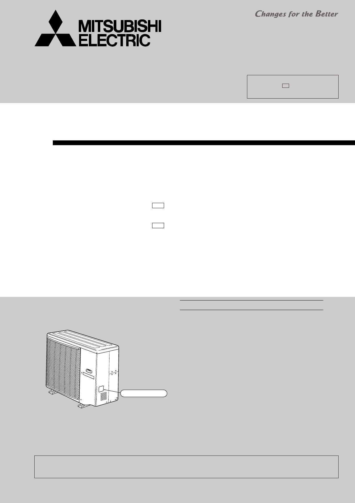
3PART NAMES AND FUNCTIONS2OUTDOOR UNITAir inletAir outlet(back and side)Model indicationMXZ-24UV-MXZ-24UV-E2E1OB287--1.qxp 03.1.16 10:29 AM Page 3
30DDCheck of LEVNoYesNoYesStartTurn on power supply to the outdoor unit after checking LEV coil is mounted to the LEV body securely.Is "click - c
31FFCheck of thermistorNormalYesNoAbnormalReconnect the connector (CN661, CN662 and CN663) and disconnect the lead wire leading to the compressor. Tur
32HHCheck of HPSInfinity0"YesNoYesStart1. Disconnect the connector CN722 in the electronic control P. C. board.2. Check the resistance of HPS aft
33TEST POINT DIAGRAM AND VOLTAGEMXZ-24UV -, MXZ-24UV -Electronic control P.C.boardE2E1Gas pipe temperature thermistorEvaporation temperature thermisto
34Noise filter P.C.boardMXZ-24UV -E1{230V ACOUTPUT{230V AC INPUT{OUTDOOR FAN 230V AC{{OUTDOOR FAN 230V AC{REVERSING VALVE 230V AC{230V ACOUTPUT{230V A
35I.P.M P.C.boardMXZ-24UV -MXZ-24UV -E2E1Relay P.C.boardMXZ-24UV -MXZ-24UV -E2E1{{{{Short12V DCHigh pressure switch12V DC{12V DC{12V DC{320V DCOB287--
36OPERATING PROCEDURE PHOTOS1.Removing the compressor(1)Remove the screws of the service panel, and remove it.Recover refrigerant gas.(2)Remove the sc
37OPERATING PROCEDURE PHOTOS3.Removing the 4-way valve(1)Remove the screws of the top panel , and remove it.(SeePhoto 1.)(2)Remove the service panel,r
38OPERATING PROCEDURE PHOTOS5.Removing the reactor(1)Remove the five screws of the top panel , and remove it.(SeePhoto 1.)(2)Disconnect the reactor le
3914Part numbers that are circled are not shown in the illustration.123456789101112131415161718192021T2W E40 301M21 17A 501M21 17E 337T2W E89
43INDOOR / OUTDOOR CORRESPONDENCE TABLE❈There is no combination other than this table.MXZ-24UV- E1 , MXZ-24UV- E2OUTDOOR UNITCombination of the conne
40123456789101112131415161718192021222324M21 AS2 232M21 17A 245T92 500 800M21 90V 646T2W E70 653T2W E95 653T2W E95 655T2W E70 651T2W
411No. Parts NameSymbolin WiringDiagramParts No.Q'ty / unitRemarksE1MXZ-24UV -T2W E59 704DRAIN SOCKET ASSEMBLY1DRAIN SOCKET O1DRAIN CAP O2E2MXZ-2
15-1. Different-diameter pipeFor different-diameterpipesMXZ-24UVMAC-454JPMAC-455JPMAC-456JPModel nameConnected pipesdiameter (mm){9.52 — {12.7 (3/8)
OB287--2.qxp 03.1.16 10:31 AM Page 43
New publication, effective Jan. 2003Specifications subject to change without notice.CCCopyright 2001 MITSUBISHI ELECTRIC ENGINEERING CO.,LTDDistribute
50709121807+0707+0907+1207+1809+0909+1209+1812+1212+1818+1807+07+0707+07+0907+07+1207+07+1807+09+0907+09+1207+09+1809+09+0909+09+129090909090909090909
6NOTE: Electrical data is for outdoor unit only.0709121807+0707+0907+1207+1809+0909+1209+1812+1212+1818+1807+07+0707+07+0907+07+1207+07+1807+09+0907+0
75SPECIFICATIONOutdoor modelIndoor units numberIndoor units total capacity (Connectable)Indoor units total capacity (Simultaneous operation)Piping tot
8NOISE CRITERIA CURVES690807060504030201063 125 250 500 1000 2000 4000 8000APPROXIMATETERESHOLD OFHEARING FORCONTINUOUSNOISENC-60NC-50NC-40NC-30NC-20N
9OUTLINES AND DIMENSIONS7MXZ-24UV -MXZ-24UV -E2E1Unit: mmOUTDOOR UNIT2310 353209008846050900250381.8531.33172333Handle formovingAir inIndoor and outdo
Related products and manuals for Split-system air conditioners Mitsubishi Electronics MXZ-24UV

 (37 pages)


 (50 pages)
© 2020, manymanuals.com. All rights reserved. | 1.369 s |
 Manymanuals.com
 Manymanuals.de
 Manymanuals.fr
 Manymanuals.it
 Manymanuals.pl
 Manymanuals.cz
 Manymanuals.es
 Manymanuals-pt.com
Comments to this Manuals